Creating the Giant LiteBrite
-
By:

Have you ever wondered what happens when you let two engineers loose on a project with a broad vision and little direction? In our case, LiteBrite happens.
Every year Cerner hosts DevCon, an internal 2-day conference for all of Cerner engineering to come together, give talks about technologies, processes, and ideas - all with a little fun sprinkled in. DevCon always has a theme, for 2019 that was set to be “The 80s.” Along with many other decorations, the Engineering Culture team had a dream of having a giant LiteBrite for attendees to interact with at the conference.
The Request
In the Fall of 2018 the Engineering Culture team approached us, Aaron Kaplan and Paul Sites, with their idea. Both of us are Cerner associates who are involved in Cerner’s MakerSpace administration, heavily involved in mentoring FIRST Robotics, and are known to be quite handy. We were asked if we could create a giant LiteBrite for DevCon to match the 80s theme. Culture team showed us a few examples, the primary one being the following YouTube video. With a few vague hints and videos, a budget of a few thousand dollars, and the goal of making something cool that lit up with pixel art, we got to work.
Research
What is “Giant”?
Talking with the Culture Team we established “giant” to be somewhere around 8 feet wide and 6ft tall. We knew we wanted it to be big enough that multiple people could play with it and that any adult could comfortably reach all the pegs. We ran with that and started to think about peg density. We wanted to have enough pegs in the board so that fairly complex images could be created.
Consulting with Cerner UX designer Jordan Lawrence, we experimented with different grid layouts and peg spacings to determine what is possible for resolution and content.
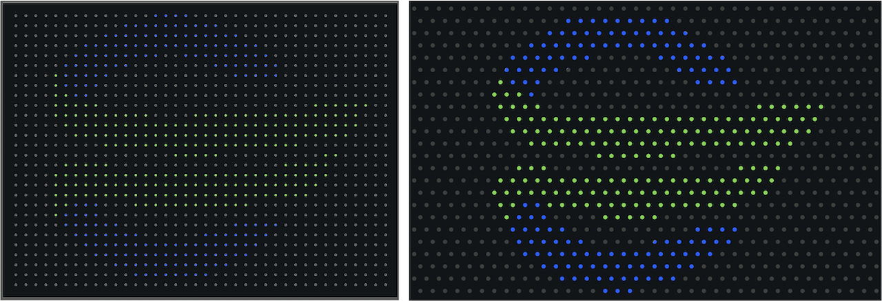
While the staggered layout gave a better result on curved designs, we ultimately decided it was less intuitive for the users, and increased our design complexity, so we settled on a square grid pattern. At this point we also decided for ease of construction that we would keep the board within the confines of a 8 ft x 4 ft sheet - a size many materials are readily available in. To balance cost with resolution, we settled on using 912 pegs total - 38 wide by 24 tall.
Design Route #1 - Classic LiteBrite
We began by exploring the most simple route to creation: a white lit background, a bunch of holes, and a variety of colored pegs. After looking at the costs of colored acrylic rods we determined that to recreate the same spectrum as the original LiteBrite, while having enough pegs of each color, would cost over $8,000 dollars, just for the pegs. This design was quickly shelved based on the cost.
Design Route #2 - Modern LiteBrite
Knowing that the “classic” option wasn’t going to work we thought back to that initial video. Pegs that are fixed, but that are interactive and respond to users pressing them.
Paul contacted the owner of the YouTube video to find out additional details of his build. We learned that his version had 225 pegs, each peg was independent (they couldn’t be remote controlled or modified), and the project cost more than $10,000.
Choosing a path - Modern LiteBrite
Knowing we could build something more advanced than a “standard” LiteBrite within our budget, we started building upon the “modern” LiteBrite concept.
We needed to ensure the following components were accounted for:
- Pegs to simulate the look of a real LiteBrite
- A way to cycle through colors
- Support multiple users tapping pegs at once.
- Overall packaging of the LiteBrite (frame, wheels, etc)
We explored countless concepts and configurations until we finally landed on the following concept:
- 1.5 inch diameter acrylic pegs
- An addressable RGB LED behind each peg for illumination
- A 3D-printed cap that retained the LED and prevented the peg from falling out
- An arcade button for receiving input
Prototyping
At this point we were excited. We demonstrated we can have an interactive peg. Excellent. Then it dawned on us we want to have nine-hundred and twelve of these. We began to realize that what was easy for one was going to become very challenging to scale.

Luckily, Adafruit sells an amazing product, the FadeCandy. This board is capable of controlling 512 LED’s, supports daisy-chaining, and it has great libraries to make displaying content moderately easy.
The next challenge to solve was reading the 912 user inputs. Microcontrollers and other devices that are designed to handle large numbers of inputs still do not come close to meeting our needs, plus, they are expensive.
Instead of creating one monolithic controller, we decided to use Arduino Nanos as addressable units of inputs. Each row of 38 inputs would be wired to a networked Nano with 5 shift registers allowing us to “expand” their inputs to 40 each.
After the design was established Hans Perera, a fellow Makerspace Admin, suggested that to get all 24 of these done, a custom printed circuit board (PCB) would be our best option. Hans then stepped up and did the development on the PCBs while we forged ahead with the rest of the project.
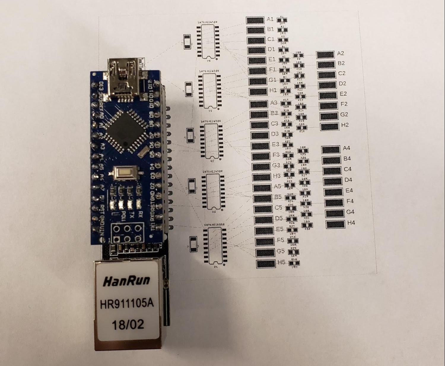
Custom printed circuit board (PCB)
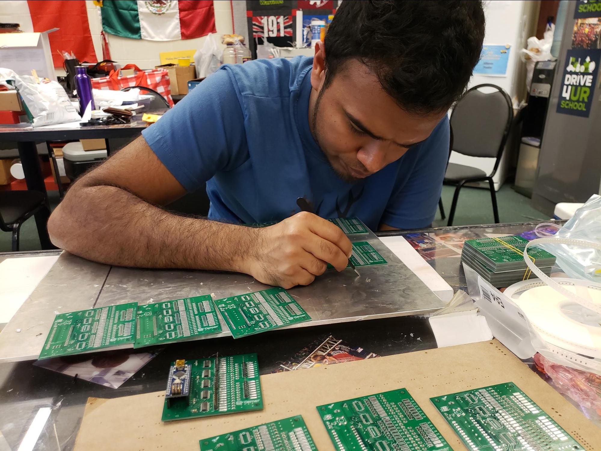
Hans placing components on the custom PCBs.
Construction
Taking Over the Robotics Shop
The Culture team was unable to provide the space or equipment needed to create the LiteBrite. Fortunately, the FIRST Robotics team we mentor (Team #1987, The Broncobots), has a full machine shop that they allowed us to use for the project.
A Strong Frame
With an estimated weight of close to 500 pounds, the LiteBrite was going to need a sturdy and stable frame. Joshua Wentworth, a Broncobots team mentor, volunteered the solution of a welded steel H-frame to hold the grid. This would allow for a compact, strong, and relatively low cost solution for the frame.
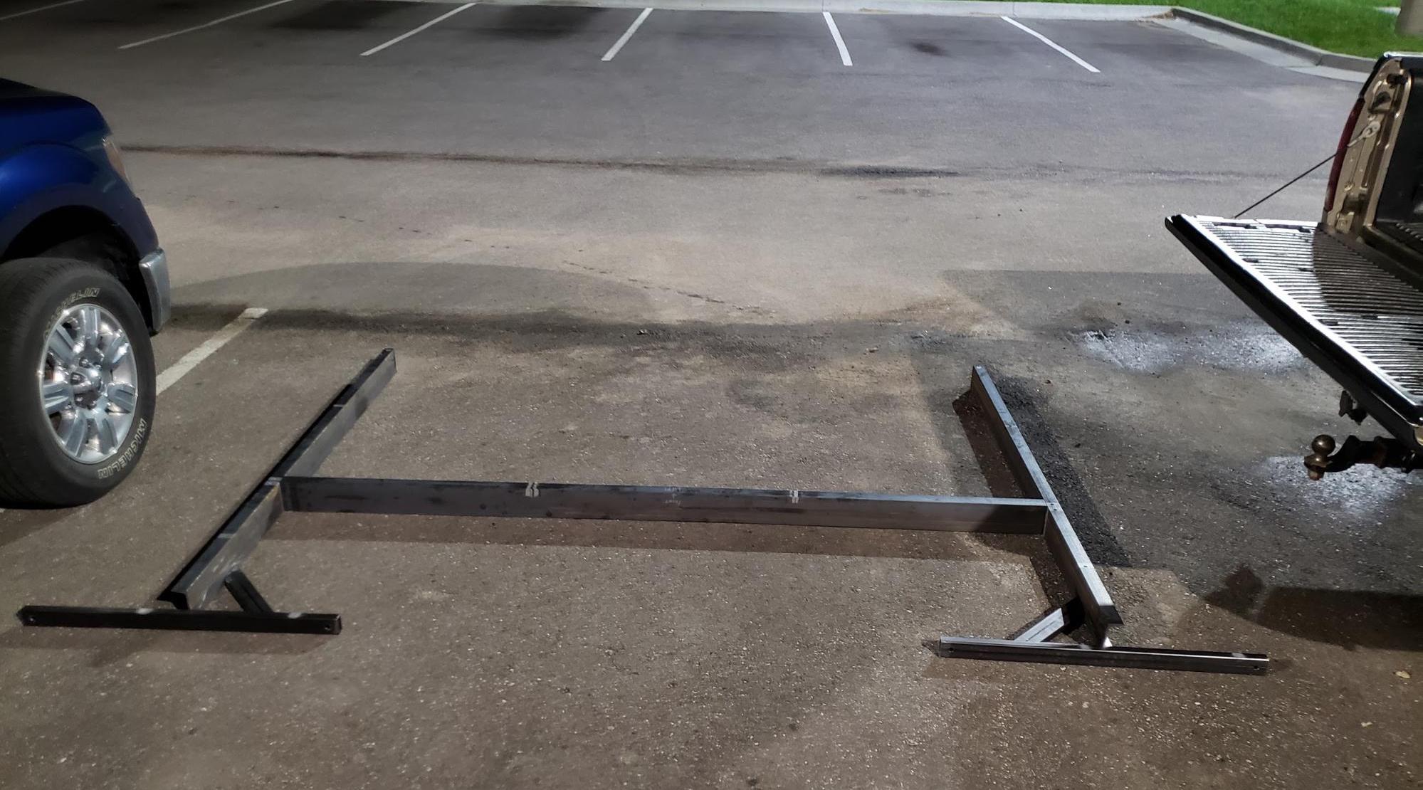
The frame pieces prior to being welded together.
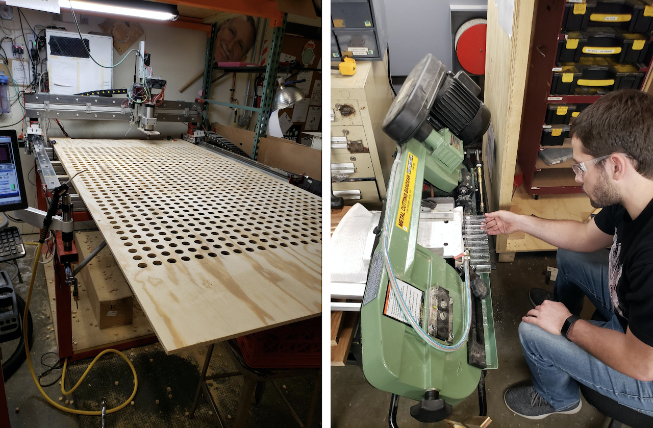
Paul used the team’s CNC router to cut the 912 holes in the main board. Pre-cut acrylic pegs are expensive, instead we purchased 4ft sticks of raw acrylic and cut them to length ourselves.
LED Strands
Each of the 912 pegs required an RGB LED, and due to the spacing of the pegs, off-the-shelf LED strips wouldn’t work. Instead, we used individual RGB LED chips, which required 6 soldered connections each, meaning 2,736 wires cut to length and stripped. Early estimates showed that we would need over 36 hours of just stripping the wires. Given our impending deadline we purchased an automatic wire stripper. Over 36 hours of wire stripping, reduced to about 2 with the automatic wire stripper.
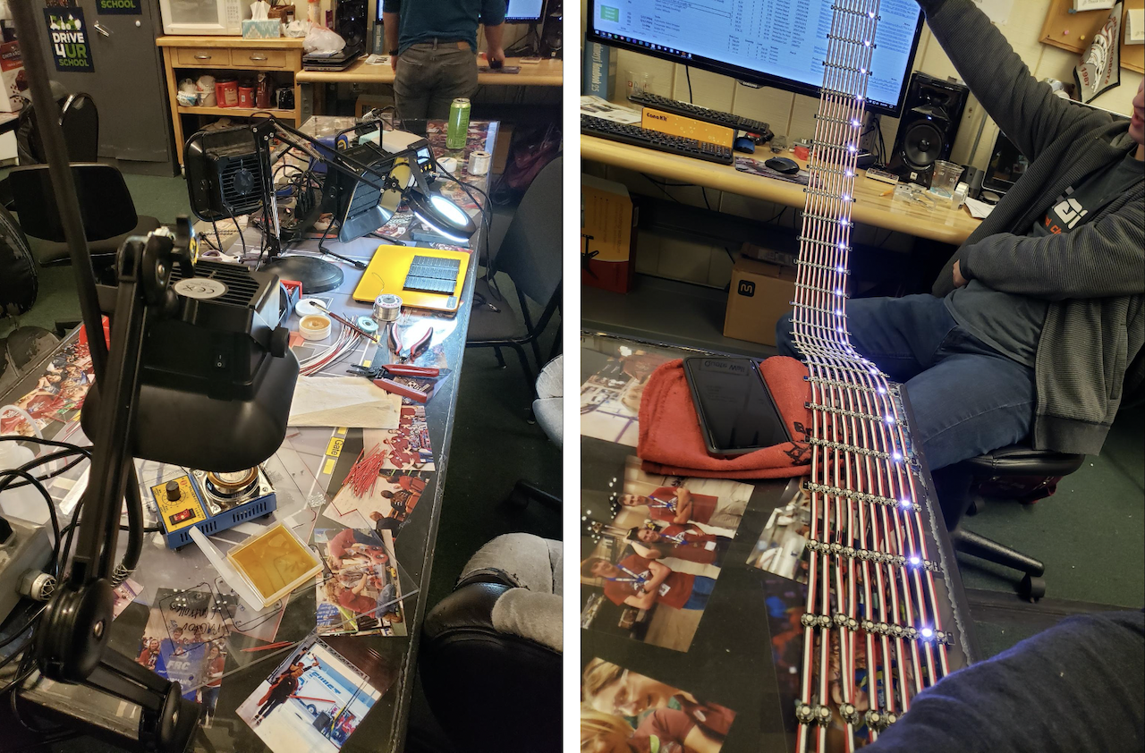
With Aaron’s soldering jig, a soldering pot for wire tinning, our LED testing controller, plus help from Cerner associates and several robotics members, we got to work mass producing our LED strands.
Buttons
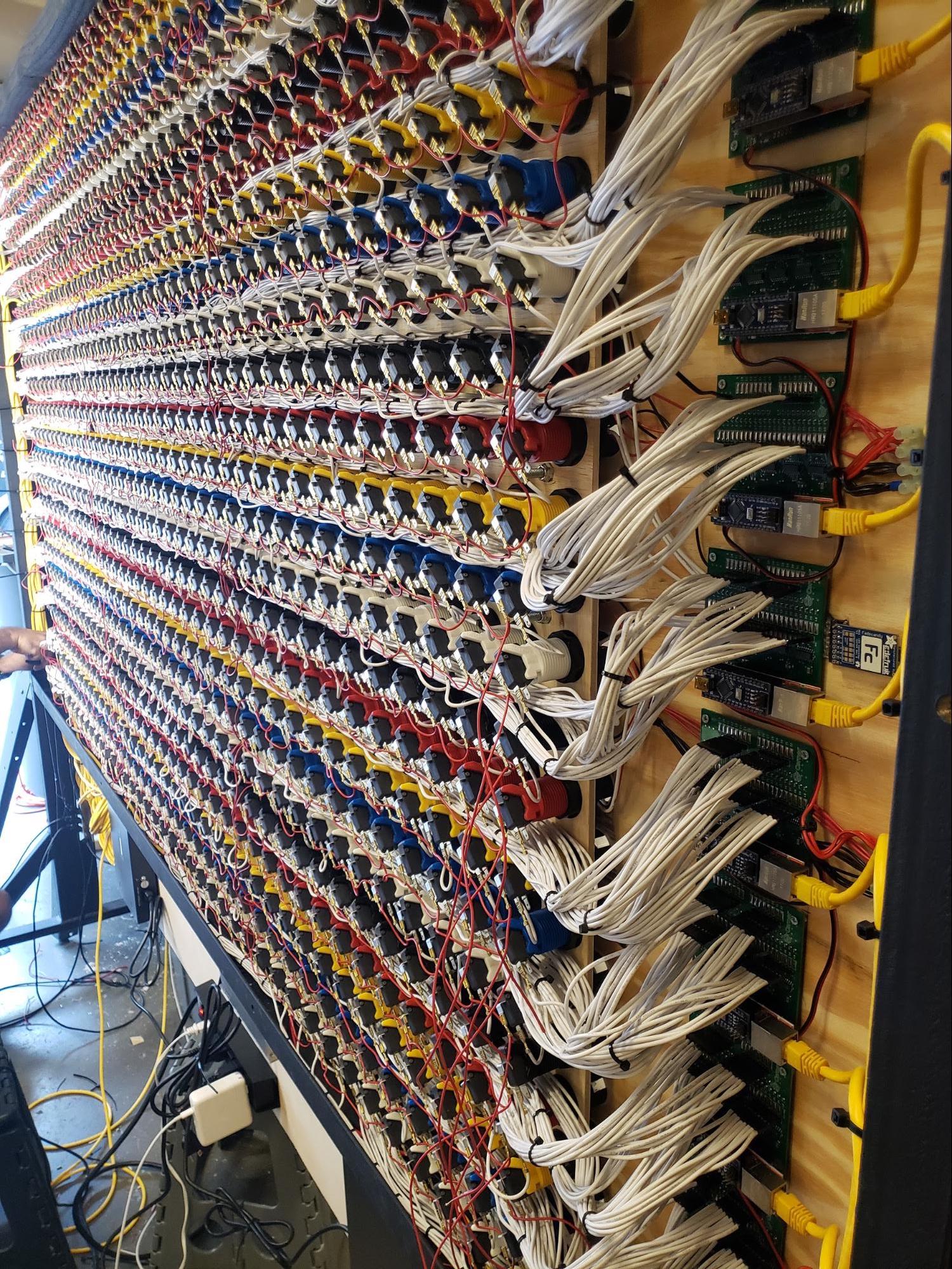
Once we had a handle on the LEDs we turned to the buttons. Each button needed power and a discrete signal wire running back to the control board. With some forethought towards service and troubleshooting significant thought was put into wire management. Buttons were distributed among 6 separate panels that were able to be disconnected and removed, simplifying assembly and troubleshooting.
We calculated the lengths of wire required to each button to prevent excess wire. Using the automatic wire stripper we precisely cut staggered lengths of wire and created a wiring harness for each row of buttons.
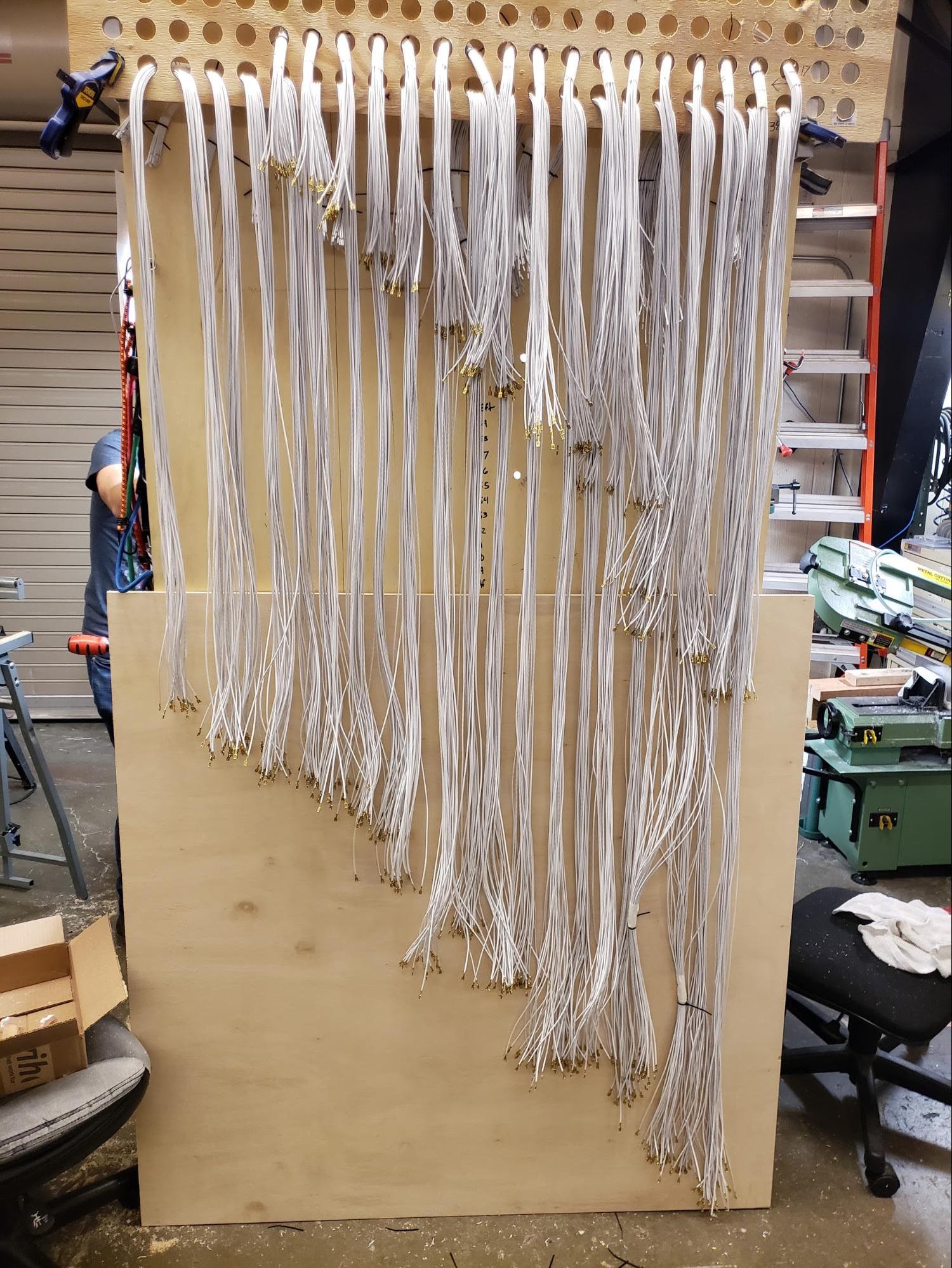
Precision cut staggered wires to use for making wiring harnesses for buttons.
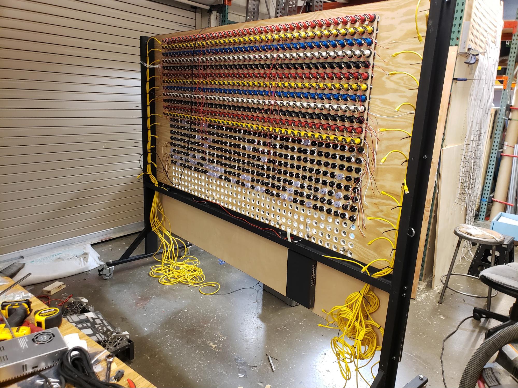
Starting to install the button panels behind the LED pegs.
Software
Time was of the essence and we could not wait for the physical hardware to be complete to develop the software. Our technology choices allowed for software development to happen in parallel to the physical construction.
We needed the color of a peg to change the instant a user pressed it to give the best possible user experience and encourage interaction. This necessitated that certain software components be optimized to minimize input lag.
Arduino
Each Arduino is responsible for the 38 buttons attached to it, and because of the multi user need, extra care was taken to ensure there were no double presses or miss counting occurring. Every Arduino is assigned a static IP address that correlates to the row it is listening to. Whenever a button in its charge is pressed, the Arduino broadcasts a UDP packet containing the state of the entire row in the form of a binary string.
01000000000000000000000000000000000000
Using the IP and the index in the string one could know the (X,Y) position of the button that was pressed. Bitwise operators were leveraged to ensure buttons were only registered once per press. With 38 buttons to connect to one tiny Arduino, all with white wires there was a high risk of connecting a button to an incorrect input.
Starting to install the button panels behind the LED pegs.
We considered labelling each wire, but that was expensive, time consuming and still error prone. Then it hit us, lets plug in buttons at random and make the controller do the hard work. From this the Arduino “training’’ mode was created. In training mode each peg is pressed in order. The Arduino records the presses and creates a map to correlate expected input index to the physical input pin. Doing this added minimal processing overhead but streamlined assembly and will aid in troubleshooting.
LiteBrite Controller
This is the main control software, it receives the UDP packets sent from the Arduinos and sets the LEDs through the FadeCandy board. When a peg is pressed the packet is sent that contains the (X,Y) coordinate for that button. The computer then updates the corresponding LED pixel at the matching coordinate. Each tap of a peg cycles a pixel through a list of available colors.
Although we set out to create a LiteBrite, what we really created is better described as an interactive dot matrix display. This has several advantages, the largest of which being able to display premade static, and dynamic content. A good example of this in practice is our clear functionality. When the clear button is pressed Pac-Man will chomp across the display eating peoples designs and resetting all pegs to black.
A big question we knew would come up is, “Is my work lost?” As the LiteBrite records ever press, we can state that no work is lost. We can even recall unique designs and play them back as a timelapse to showcase people’s work.
By collecting this data we also know exactly how many presses the LiteBrite has had. As of the time of this writing, we’ve had 443,449 presses and counting!
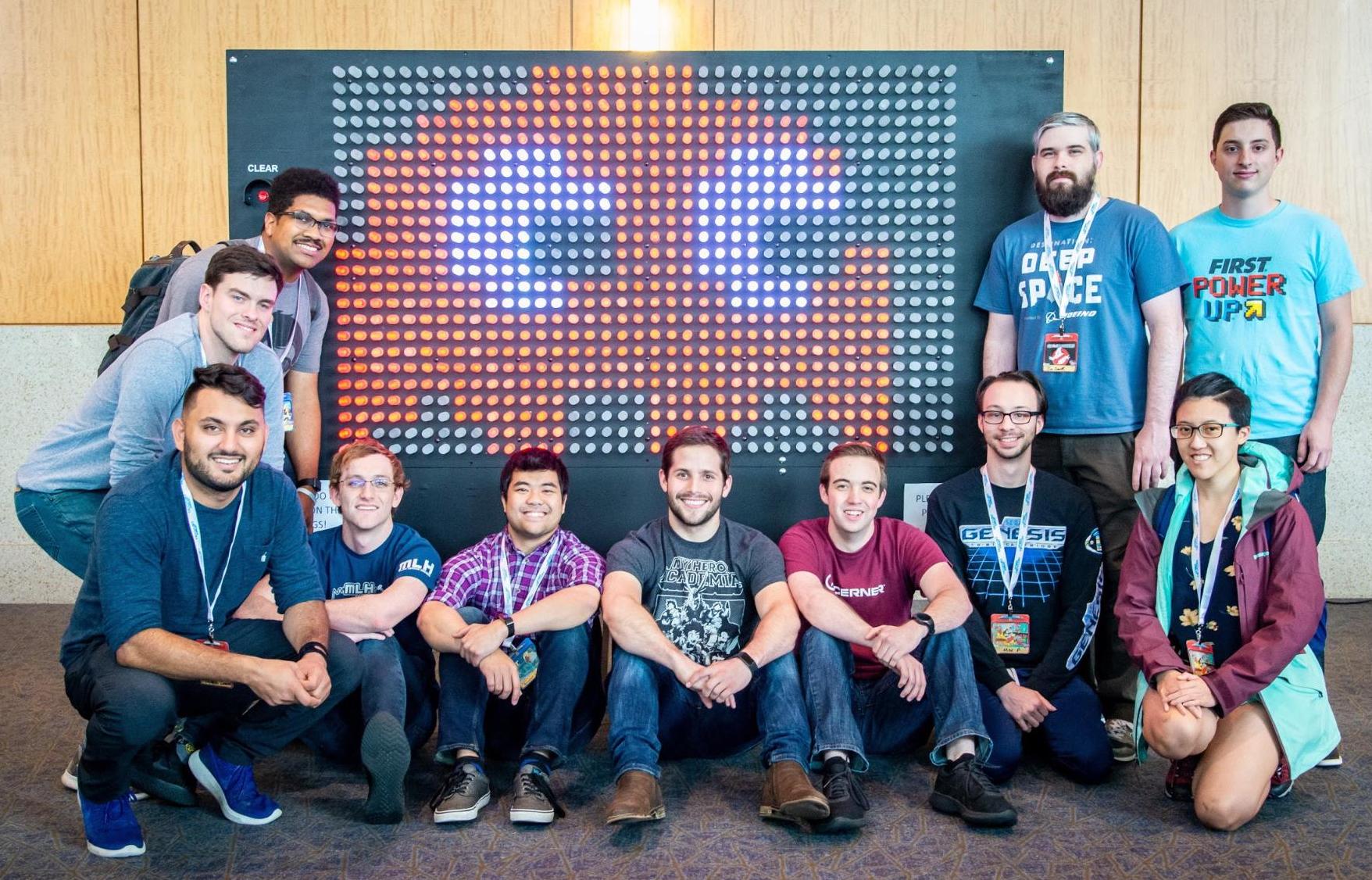
Lighting it Up

Ultimately, LiteBrite was completed at about 1:10 a.m. the first day of the DevCon event. It was loaded into a trailer and delivered hours before the event started that morning.
LiteBrite was a whirlwind of a project that involved at least 1,100 people-hours over the course of around a month and a half. Although we led the primary design and construction, over a dozen people volunteered their time to help us light up DevCon.
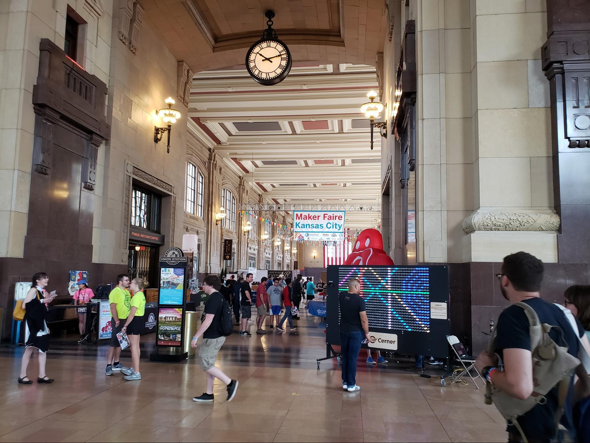
Post-DevCon
LiteBrite has occasionally made appearances around Kansas City, appearing front and center at Maker Faire for over 17,000 attendees to interact with.
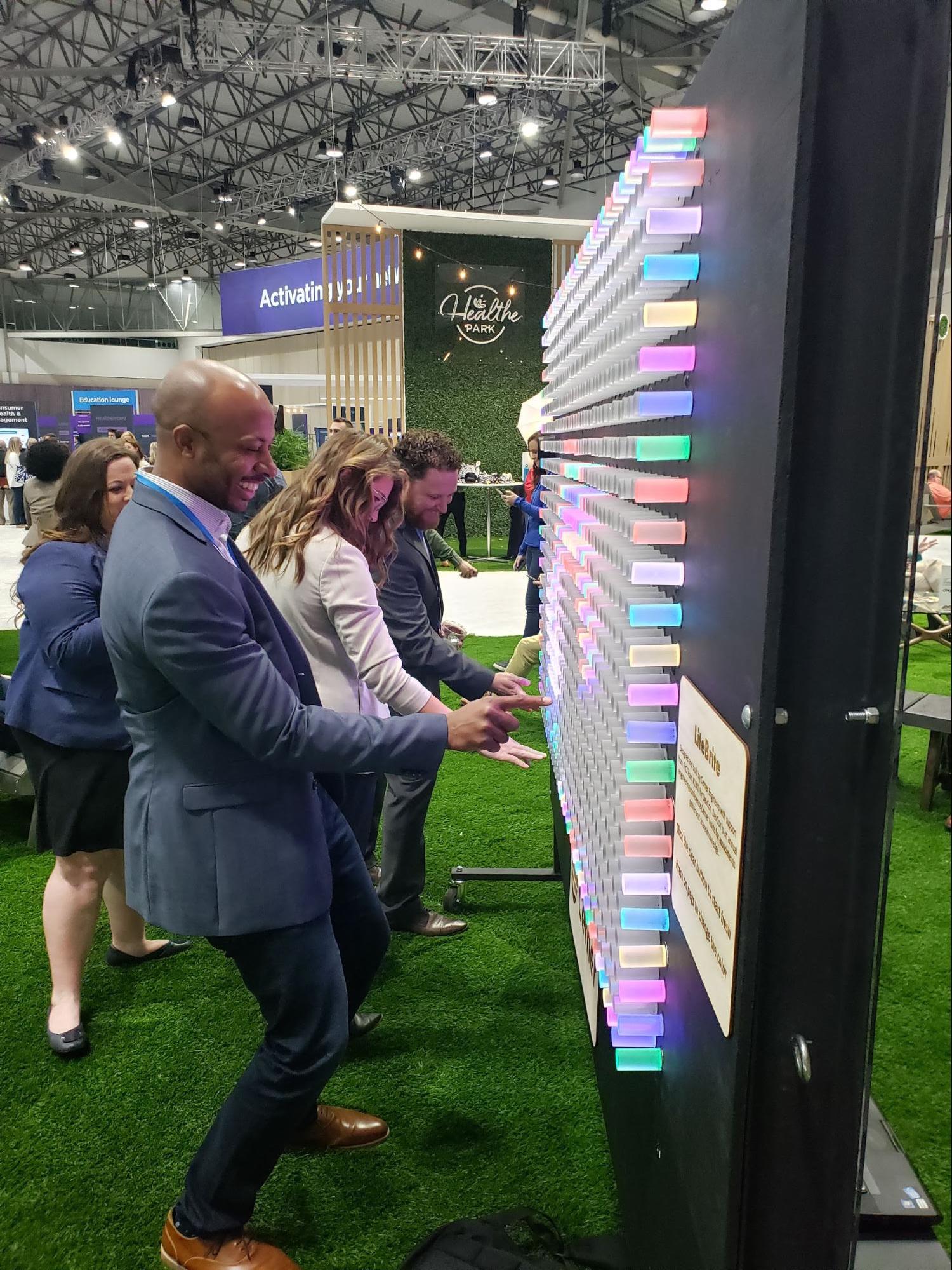
LiteBrite was invited to Cerner Health Conference in October 2019.
Today, when LiteBrite isn’t traveling it lives at the entrance to Cerner’s Innovations Campus. It greets associates every morning with a hot cup of coffee, plays back select LiteBrite creations, and encourages associates to take some time to create.
This article includes contributions from Aaron Kaplan.